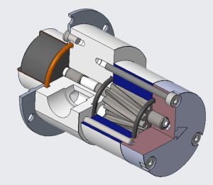
The rotation direction of a gear pump determines how fluid moves through the system. Incorrect rotation can disrupt flow, reduce efficiency, and damage components. Identifying the correct rotation ensures smooth operation and prevents costly failures. This guide explains how to identify rotation direction, whether it can be reversed, and steps to change it safely.
How to Identify Gear Pump Rotation Direction
Identifying rotation arrows or markings
Manufacturers often include rotation arrows or markings on the gear pump housing. These indicators show the intended rotation direction, whether clockwise or counterclockwise. Look for these markings near the shaft or on the pump body. They provide a quick and reliable way to confirm the correct rotation. If the markings are unclear or missing, consult the manufacturer’s manual for clarification.
Determining suction and discharge ports
The suction port and discharge port locations also help identify the rotation direction. In most gear pumps, the suction port is larger and positioned on the side where fluid enters the pump. The discharge port, typically smaller, is located where fluid exits under pressure. For a pump with clockwise rotation, the suction port is usually on the left side when viewed from the drive end. Observing these ports ensures proper installation and operation.
Recognizing the role of the pressure relief valve
The pressure relief valve plays a critical role in protecting the gear pump from overpressure. Its position can also indicate the rotation direction. For a pump with clockwise rotation, the valve is often aligned with the discharge port. This alignment ensures excess pressure is relieved efficiently. Always verify the valve’s placement to confirm the pump’s rotation and prevent potential damage.
Can You Reverse the Rotation of a Gear Pump?
Understanding reversible and non-reversible models
Gear pumps come in two main types: reversible and non-reversible. Reversible models allow the rotation direction to be changed, enabling both clockwise and anti-clockwise operation. These pumps are designed with internal components that can handle fluid flow in either direction. Non-reversible models, however, operate in only one direction. Their internal design, including the drive shaft gear and lubrication paths, supports a single rotation direction. Identifying the type of gear pump is essential before attempting any modifications. The manufacturer’s manual often provides this information.
Evaluating system compatibility for hydro gear pumps
Hydro gear pumps are commonly used in hydraulic systems. Before reversing the rotation direction, users must evaluate system compatibility. The suction and discharge ports, as well as the pressure relief valve, must align correctly with the new rotation. Incorrect alignment can disrupt fluid flow and reduce efficiency. Additionally, the drive shaft gear must remain properly lubricated to prevent wear. Consulting the manufacturer’s guidelines ensures the pump and system can handle the change without compromising performance.
Risks of incorrect or anti-clockwise rotation
Operating a gear pump in the wrong direction can cause significant damage. Incorrect rotation may lead to cavitation, overheating, or seal failure. Anti-clockwise rotation in a pump designed for clockwise rotation can disrupt the lubrication path, causing internal components to wear prematurely. Testing the pump after reassembly ensures it operates with the correct rotation. Taking these precautions minimizes risks and extends the pump’s lifespan.
Steps to Change the Rotation of a Gear Pump
Reviewing the manufacturer’s manual
Before attempting to change the rotation of a gear pump, reviewing the manufacturer’s manual is essential. The manual provides specific instructions tailored to the pump model. It outlines whether the pump supports reversible operation and details the steps required to change direction. Skipping this step can lead to improper adjustments or damage to internal components. Users should also confirm the compatibility of the hydro gear pump with the intended system setup. This ensures the suction and discharge ports, as well as the drive shaft gear, align correctly after the modification.
Adjusting internal components
Changing the rotation direction often involves adjusting internal components. Start by disassembling the pump carefully to access the internal mechanisms. Rotate the drive shaft gear to align it with the new direction of flow. Some models may require repositioning the pressure relief valve or modifying the lubrication path to support the new rotation. Ensure all parts are reassembled securely to prevent leaks or operational issues. Using the correct tools and following the manual’s guidance minimizes the risk of errors during this process.
Testing for correct rotation after reassembly
After reassembly, testing the pump is crucial to verify the new rotation direction. Connect the pump to the system and observe the flow of fluid. For a clockwise rotation, ensure the suction port draws fluid in while the discharge port expels it under pressure. Monitor the pump for unusual noises, leaks, or overheating, which may indicate improper adjustments. Testing ensures the pump operates efficiently and prevents potential damage caused by incorrect rotation.
Key Considerations for Changing Rotation Direction
Ensuring lubrication path compatibility
The lubrication path inside a gear pump plays a vital role in maintaining smooth operation. When changing the rotation direction, the lubrication path must align with the new flow direction. A misaligned path can lead to insufficient lubrication, causing wear on the drive shaft gear and other internal components. Users should inspect the pump’s internal design to ensure the lubrication channels support the intended rotation. For hydro gear pumps, this step is especially critical due to their reliance on precise lubrication for high-pressure performance. Following the manufacturer’s guidelines helps avoid operational issues.
Aligning suction and discharge ports
The suction port and discharge port must align correctly after altering the rotation direction. The suction port should always draw fluid into the pump, while the discharge port expels it under pressure. Reversing the rotation without adjusting these ports can disrupt fluid flow, reducing efficiency and potentially damaging the pump. Users should verify the port alignment during reassembly. Observing the fluid flow during testing ensures the ports function as intended. Proper alignment prevents operational failures and maintains system efficiency.
Verifying pressure relief valve functionality
The pressure relief valve protects the pump from damage caused by high pressure. Its position must correspond to the discharge port after the rotation change. If the valve remains misaligned, it may fail to relieve excess pressure, leading to potential system failure. Users should reposition the valve as needed and test its functionality during operation. Ensuring the valve operates correctly safeguards the pump and extends its lifespan. Regular maintenance checks further enhance reliability.
Conclusion
Understanding gear pump rotation direction ensures efficient operation and prevents damage. Following manufacturer guidelines is essential for maintaining system compatibility. For complex tasks, consulting professionals is highly recommended. Pumps designed for bidirectional rotation or bi-directional pumping require careful adjustments to function correctly, ensuring optimal performance and longevity.


